Week 02: Computer-aided Design

What does Computer-Aided Design mean?
CAD (Computer-Aided Design) encompasses all programs that assist in constructing, designing, planning, and building products (from clothing to cars). First, we discussed the beginnings and evolution of CAD. CAD was first used in 1957, and we explored the different milestones up to the 2000s. CAD is utilized in several diverse industries such as architecture, engineering, and electronics.
We also explored the distinction between vectors and pixels. We learned that all the machines we will be working with in the next weeks operate with vectors. Working with vector files has many advantages, most notably, you don't lose quality. Vectors work with simple geometric shapes. Everything is constructed from these basic elements. Pixels consist of very small points (which we don't really see). There are different tools that can be used for both raster and vector graphics.
Raster Graphic Tools
- GIMP (one of the biggest open-source softwares)
- KRITA
- Adobe Photoshop (the biggest Raster Editor)
- PIXLR (webbased)
- Photopea (like Photoshop from a few years ago)
Vector Graphic Tools
- Inkscape (big Community)
- Adobe Illustrator
- CorelDRAW
- Linearity Curve Design
- Vectr
- Freemium
- DrawSVG
- LibreCAD
Inkscape
 I chose Inkscape for my 2D design. Upon opening a new file, I embarked on creating multiple sketches, allowing me to experiment with various tools and techniques.
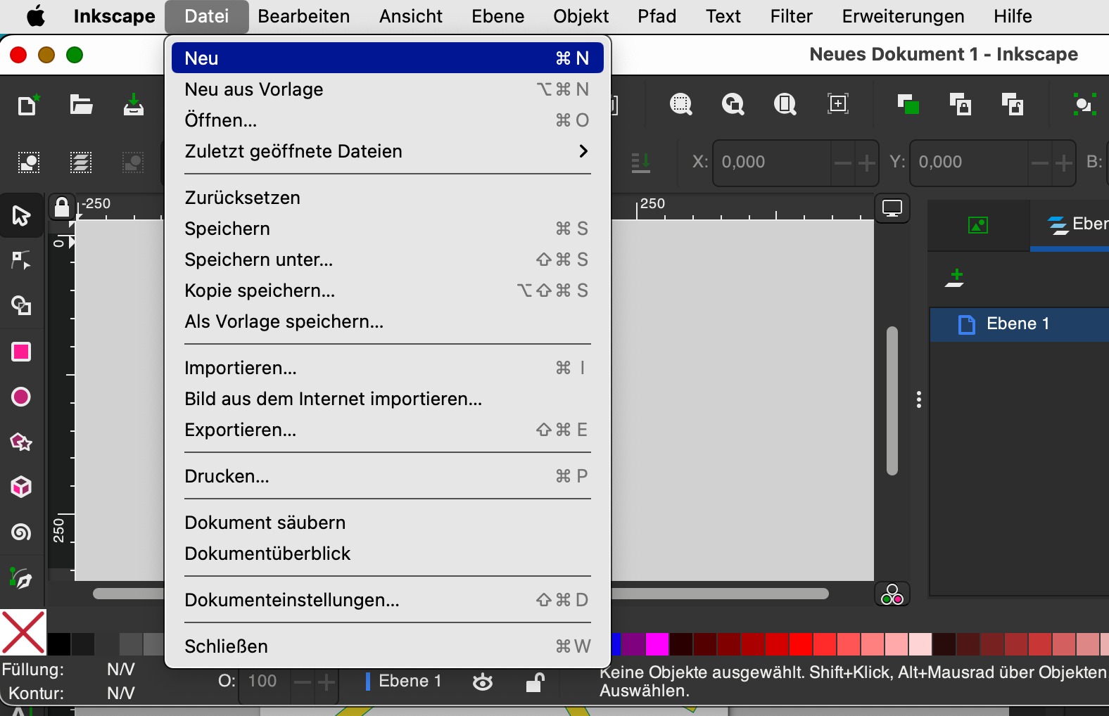 As a first step, I opened a new file:
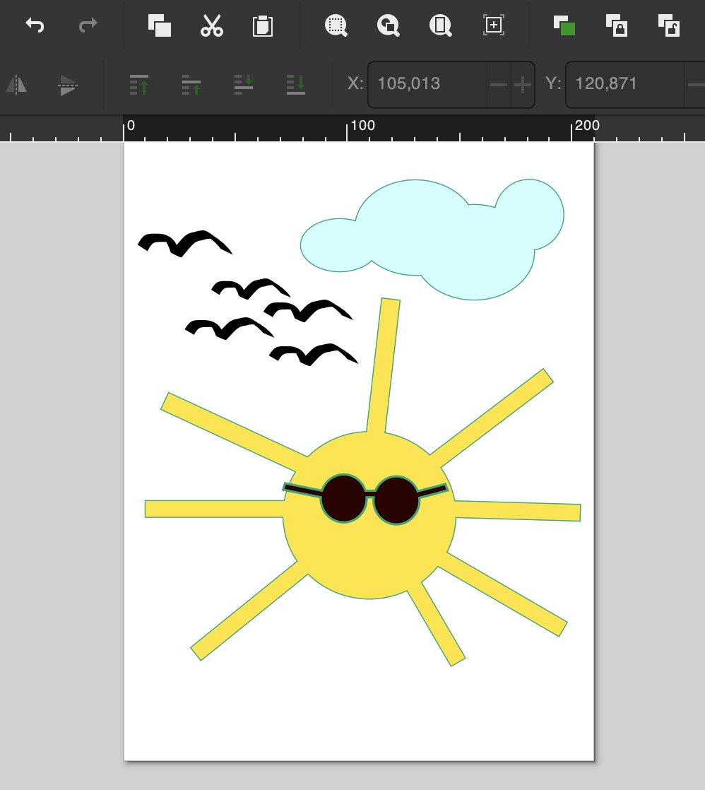
 I then created a simple drawing by using the drawing elements from the left toolbox.
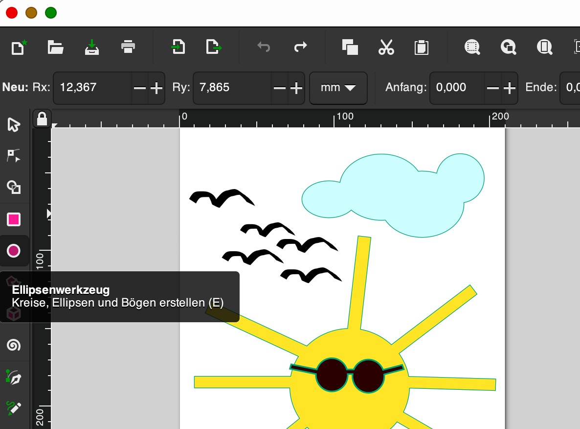 For example, to draw the cloud, I used the ellipse tool.
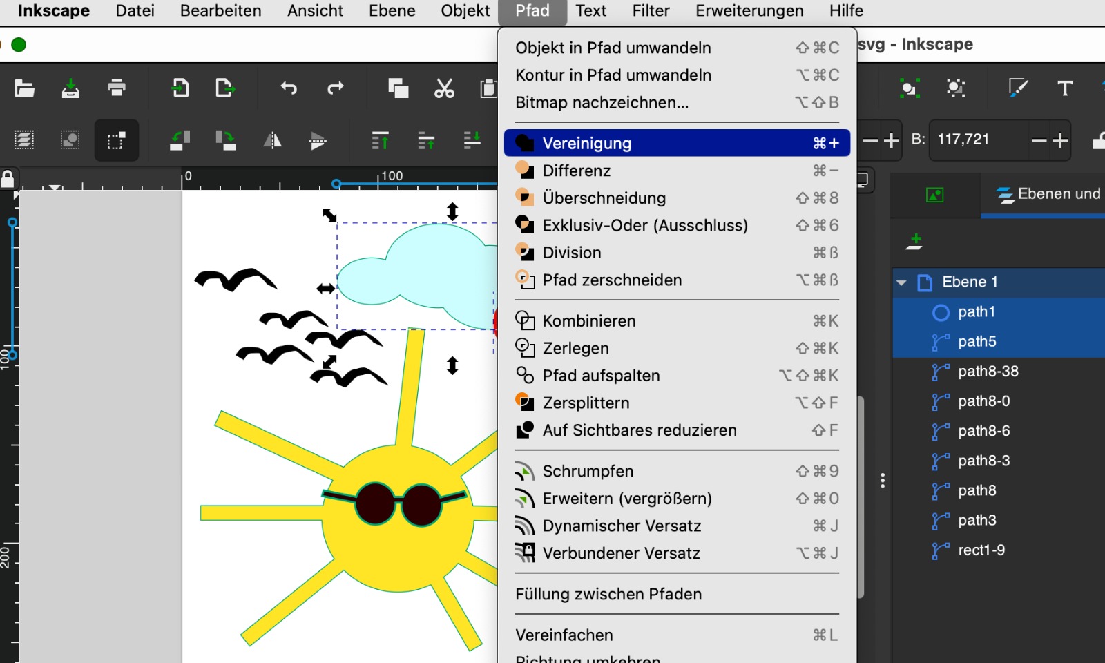 I then combined the individual ellipses into one object using the Path > Union tool.
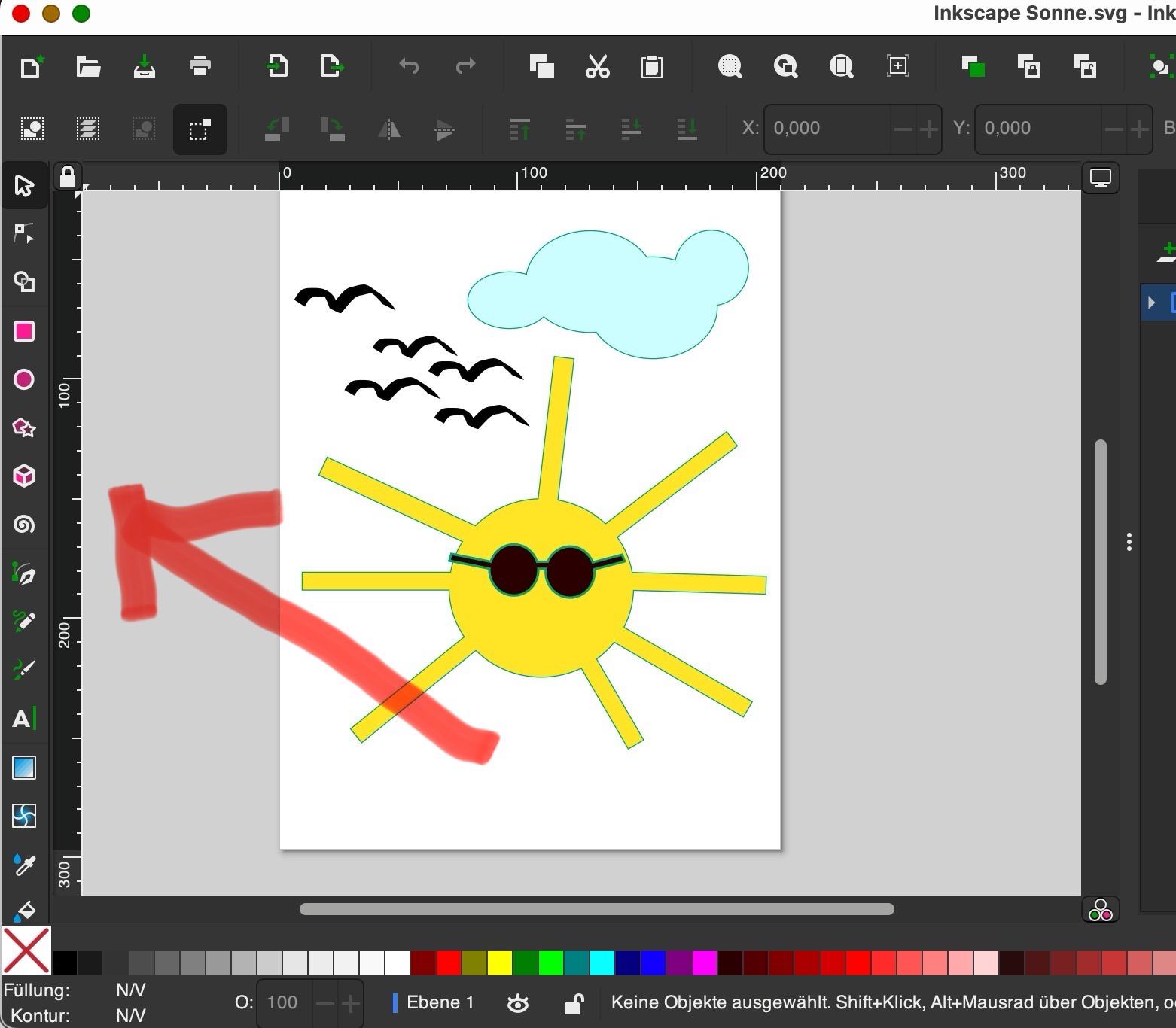
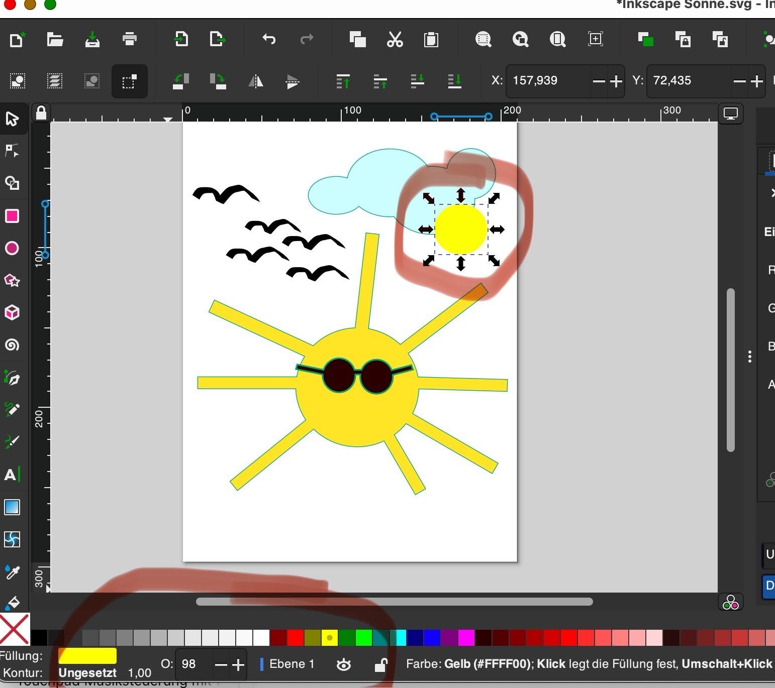 I could easily change the color through the menu on the screen edge.
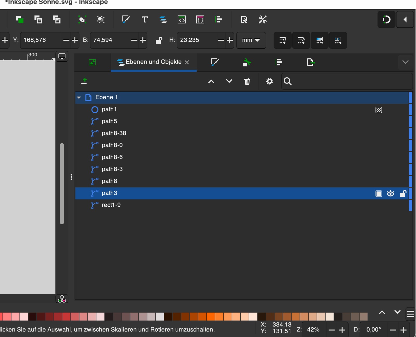 It was also important for me to familiarize myself with the functions of objects and layers, as I used them frequently later on. These were especially essential when creating the KiCad files.
TinkerCad
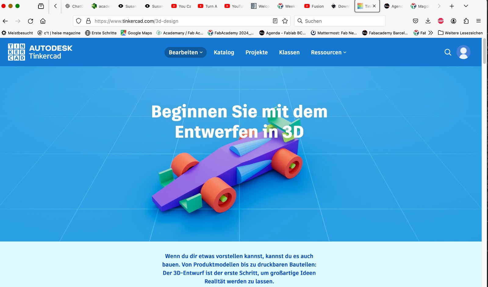 For 3D design we learned how to use several tools such as Fusion, Blender, Rhino, and TinkerCad. Since I had no prior experience with these tools, I opted to begin with Tinkercad. First, because it appeared to be the most user-friendly among the ones we were introduced to. Second, because my interest lies in using these tools with children. Tinkercad is also utilized by teachers and students. I started by watching a video tutorial.
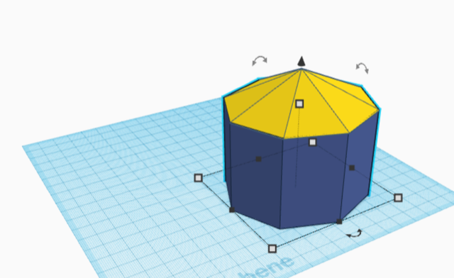
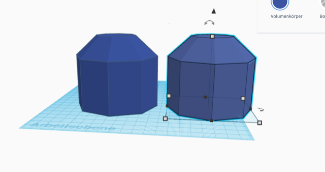
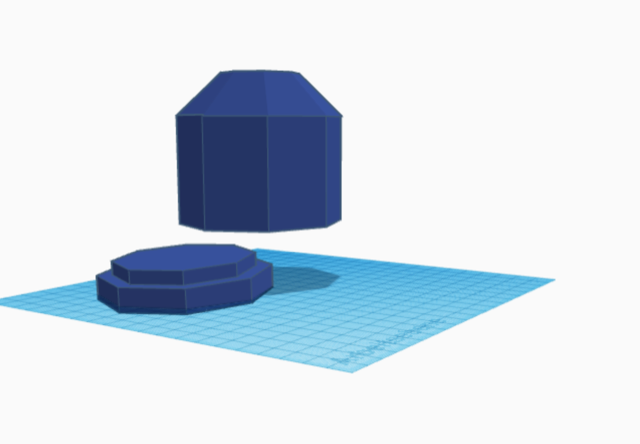
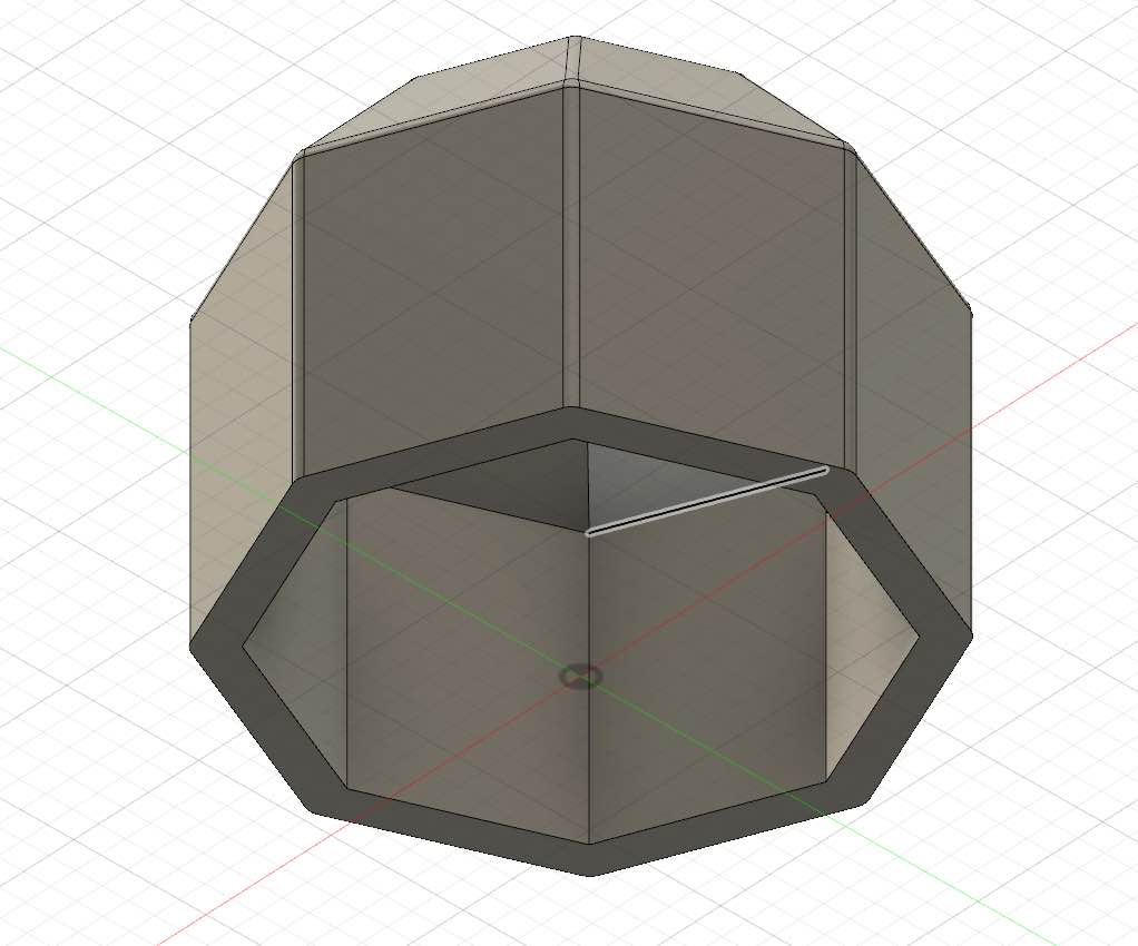
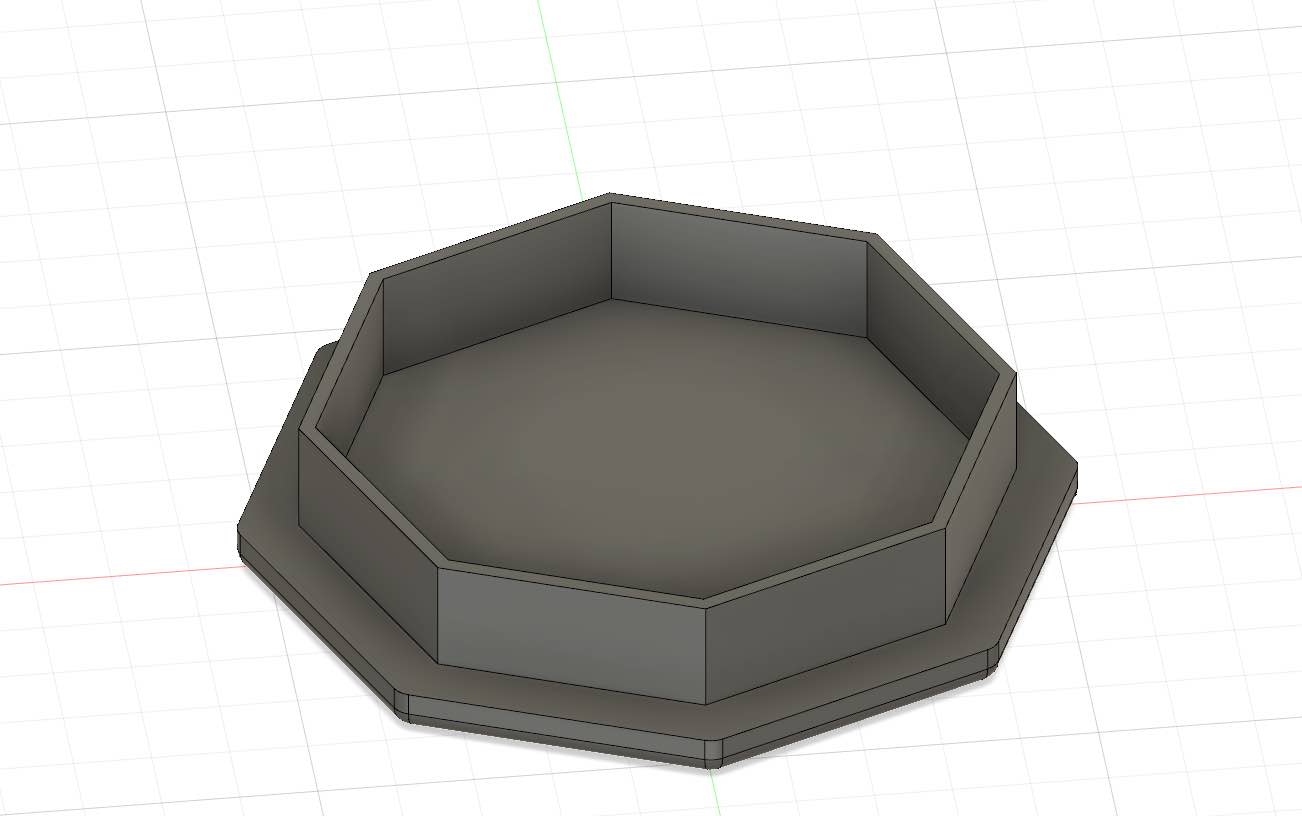
To take my first steps, I decided to construct a box that could be similar to my final project. First, I built a box with 8 sides. After that, I created a top. In order to accommodate the electronics for my final project inside, I hollowed out the box and also constructed a bottom. This way, the top can be attached to the bottom.
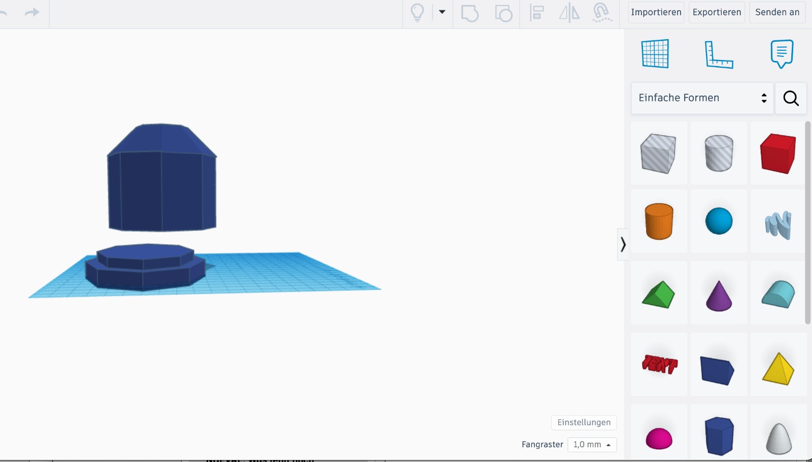 To create simple shapes in TinkerCad, the elements on the right side of the screen can be used. To select them, they are dragged onto the workplane with the mouse. Instead of solid bodies, holes can also be dragged onto the workplane.
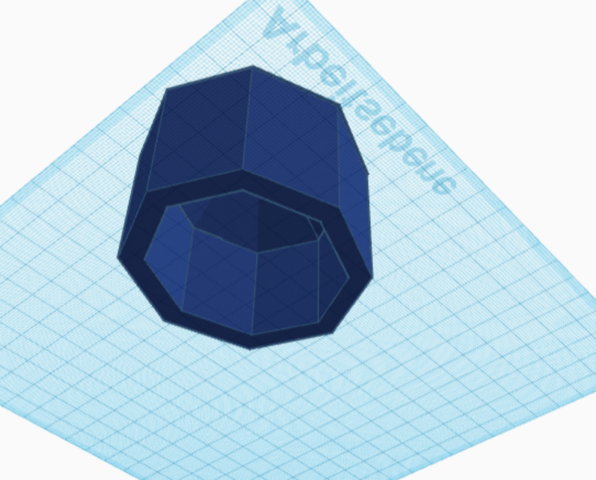
 After selecting two elements, it is also possible to decide whether the two elements should be combined into one or if a hole should be made. In the case of a hole, one element is cut into another. This allowed me to shape a can from my element.
Fusion 360
 After my first experience in Tinkercad, I decided to recreate a similar design in Fusion 360. Although I found Fusion intriguing, the initial steps proved challenging. I opted to start by watching a video tutorial, but it was difficult to find a suitable one. Finally, I found a German tutorial that was very helpful.
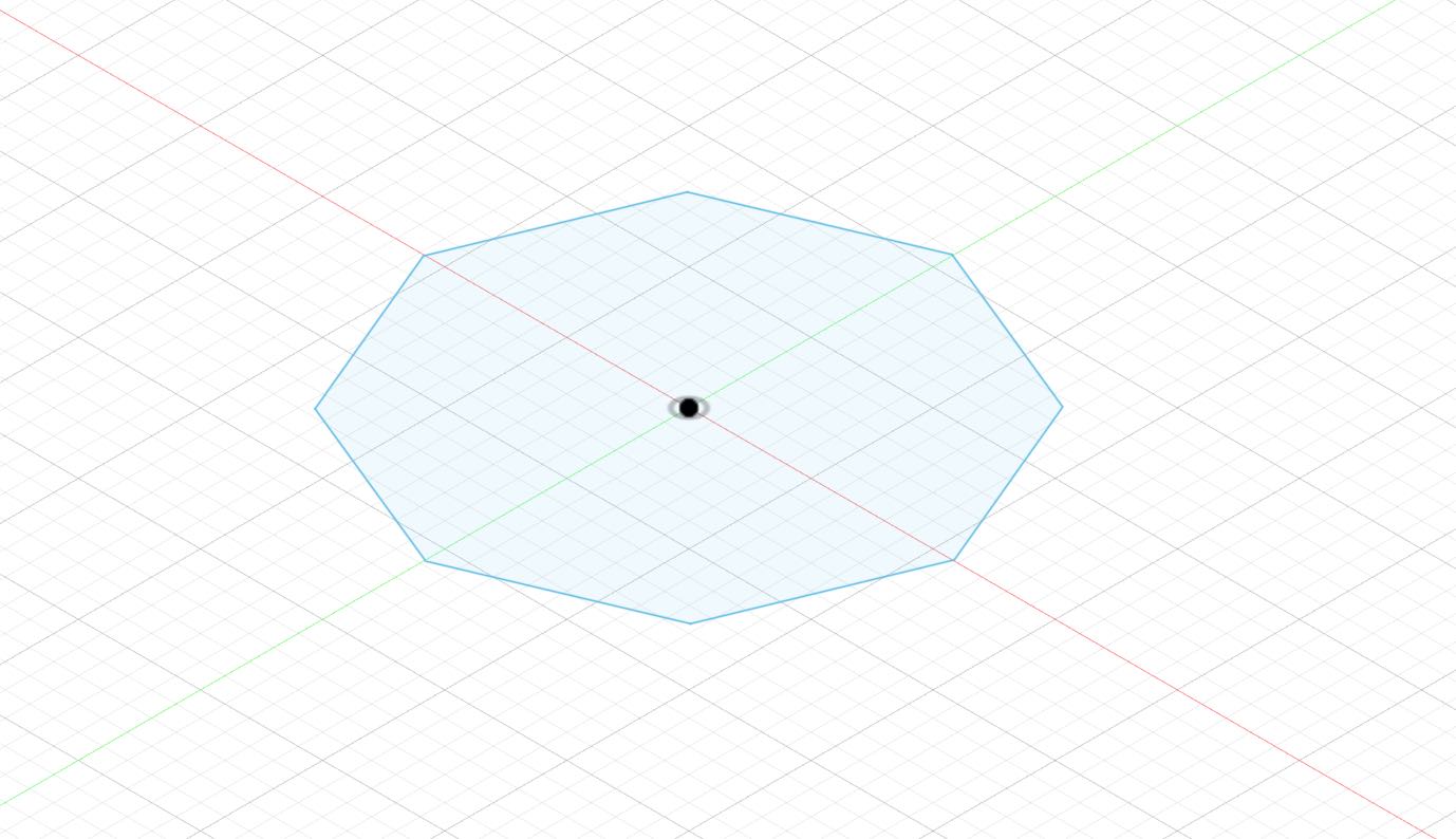
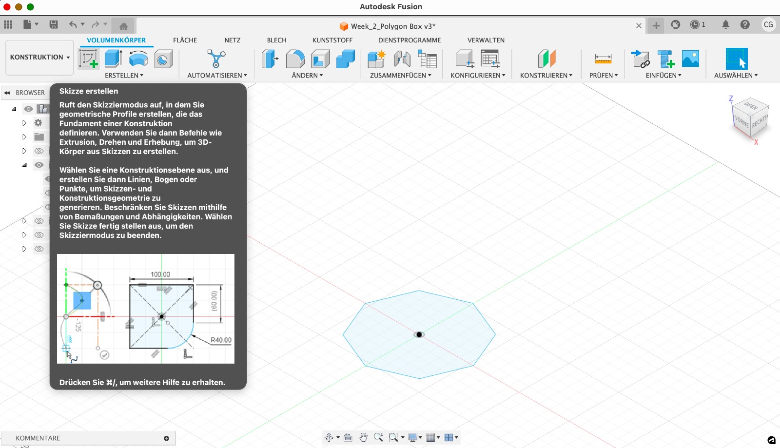 Creating a Sketch: To create an object in Fusion 360, you typically start by creating a new sketch. I selected the "Create Sketch" option and then chose a plane/surface to draw on.
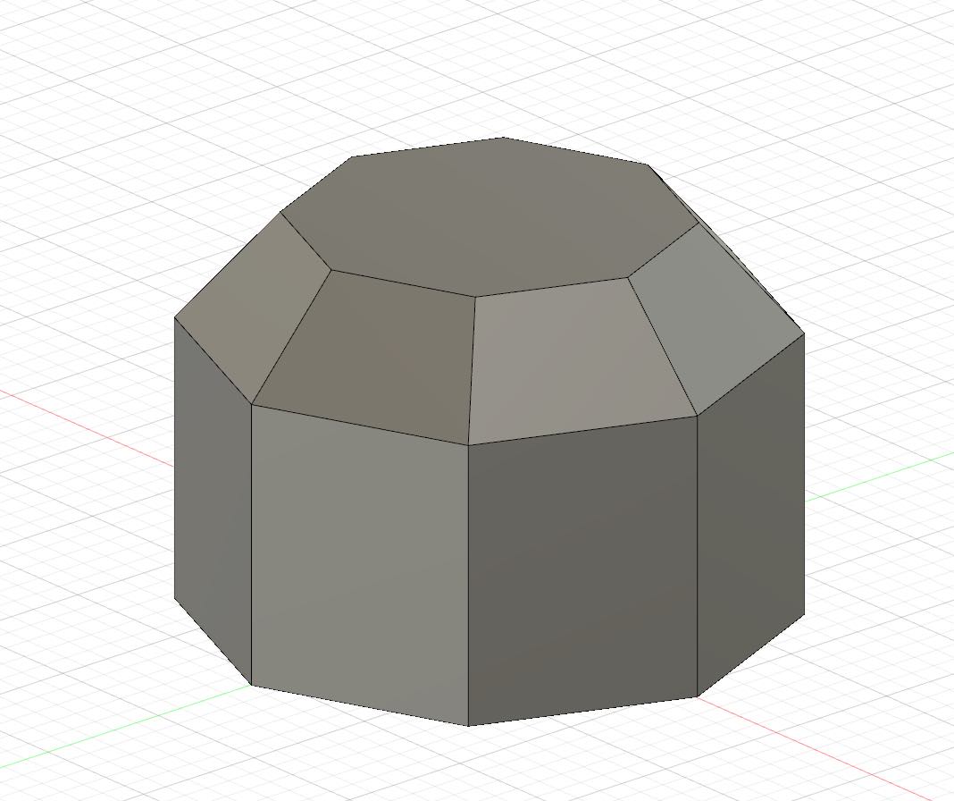
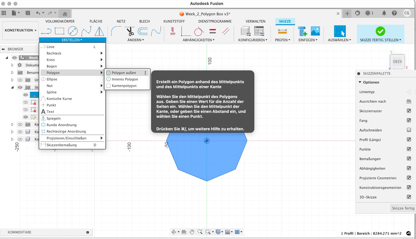 To draw a similar object as in Tinkercad, I chose the Polygon drawing tool and specified 8 sides for the polygon. Additionally, I set the size of the polygon.
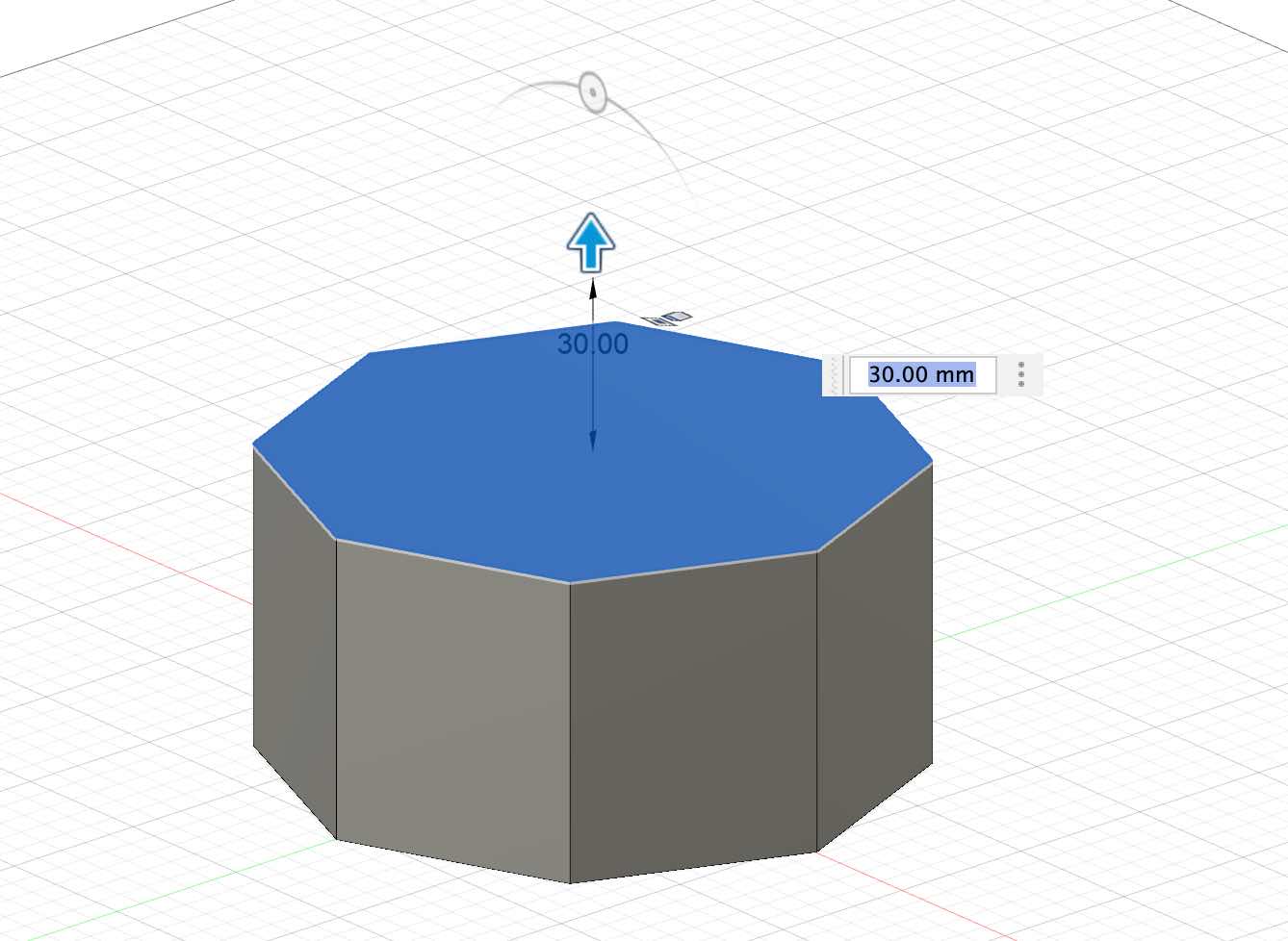
 Next, I extruded the sketch. This means I created a solid body from the sketch. I selected the "Extrude" tool in the toolbar. It is easy to pull the extrusion upwards or input a specific number if the exact height of the extrusion is already known.
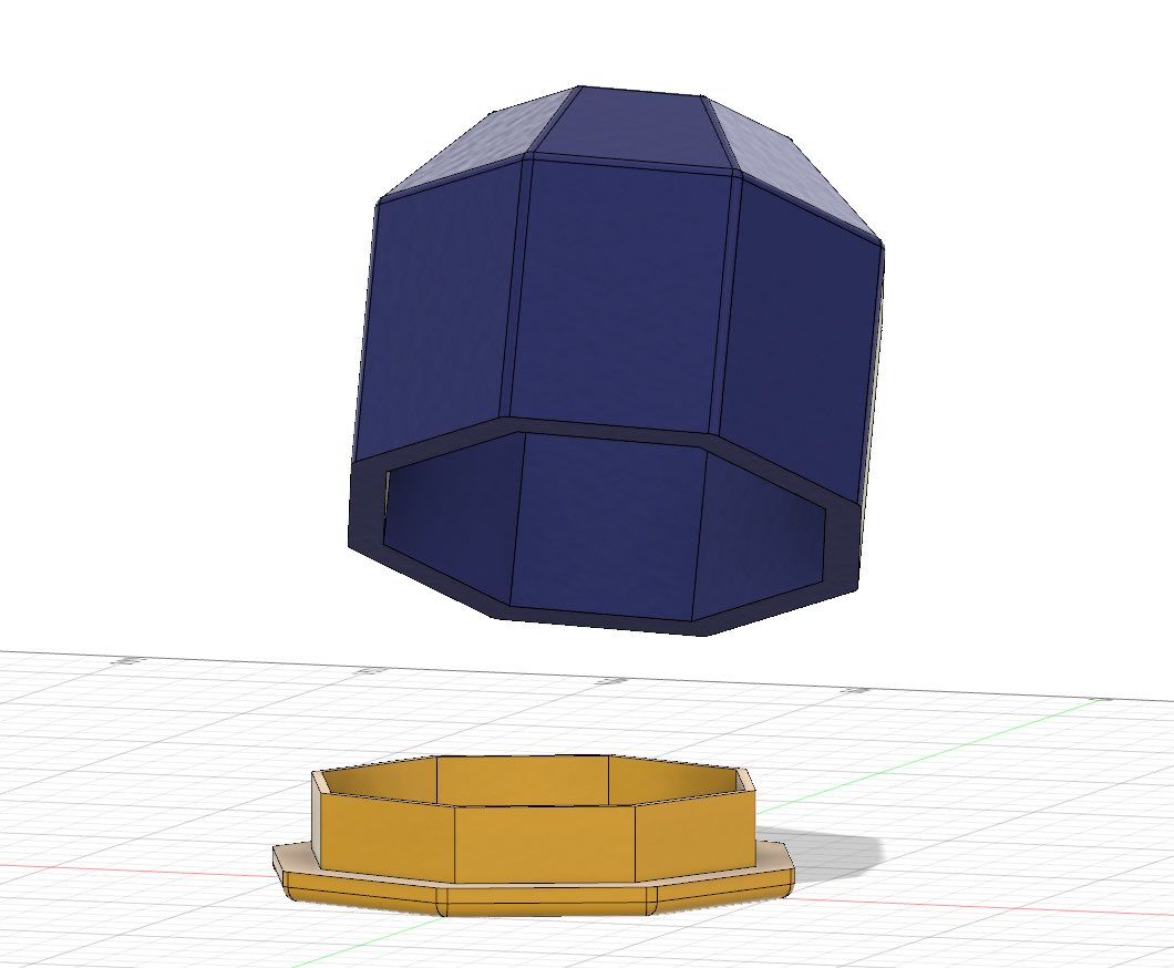
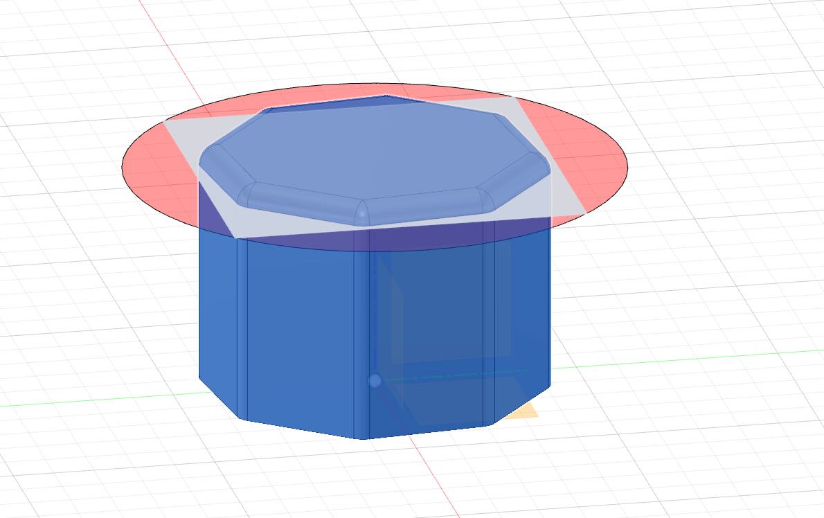
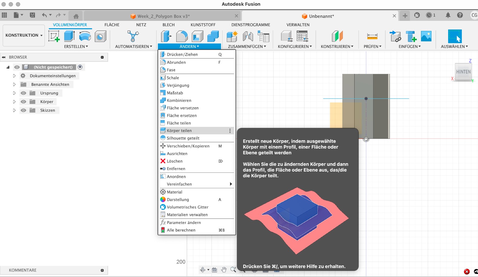 To make the box into two parts (lid and bottom), it is possible to cut the box. For this, you need a plane or a cutting line. Using the Split Body tool from the Modify toolbar, the body can be split into two parts.
 To change the color or material, you can select the appearance and material options through "Modify," allowing you to alter the appearance of the body.
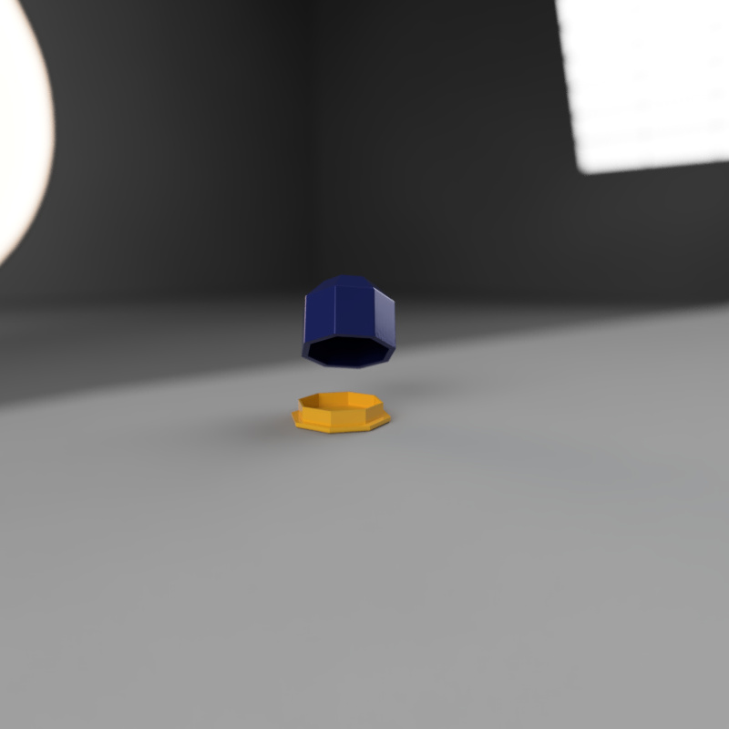
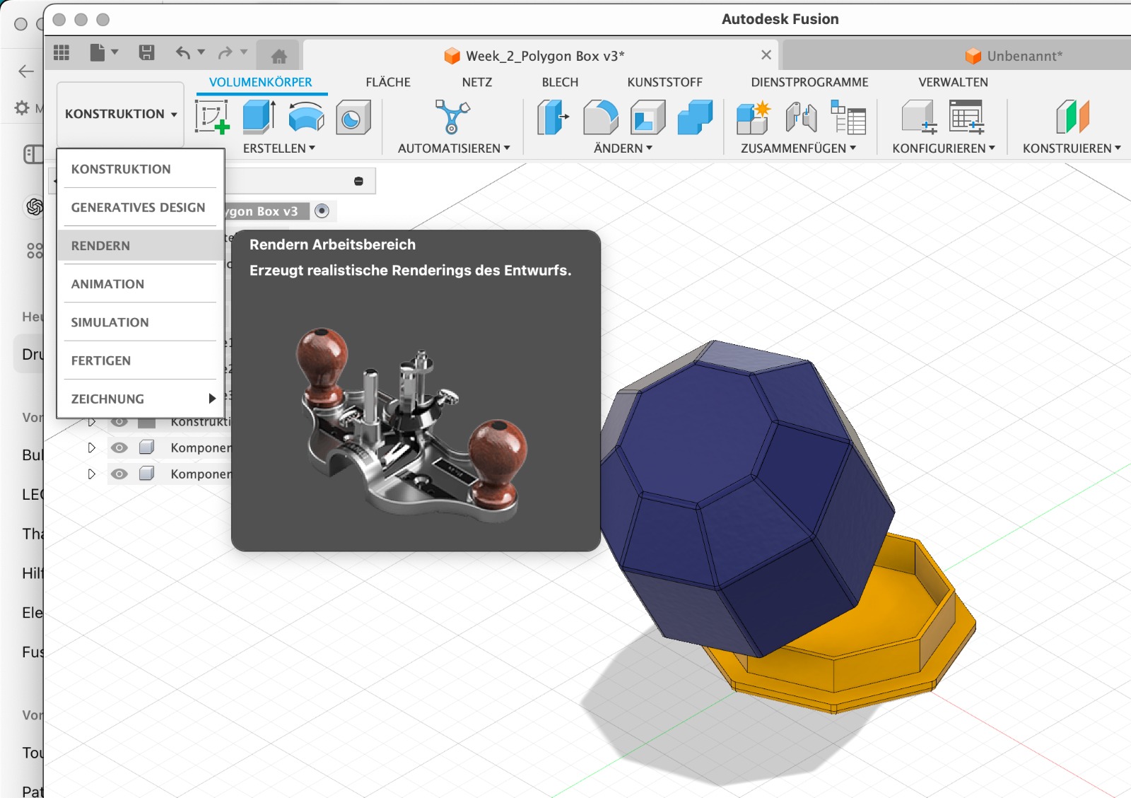 To do a rendering an animation I switched to the Render workspace. First, I applied materials and colors to my model using the appearance settings. Then, I configured the scene by adjusting the lighting and background. I positioned the camera and initiated the rendering process by clicking Render. Finally, I saved the rendered image.
To create an animation, I switched to the Animation workspace. I used the timeline at the bottom to create keyframes, animating the movement, rotation, or scaling of parts over time. I adjusted the camera settings to define the viewpoints. After previewing the animation, I rendered the animation by clicking Publish or Render. Once the rendering was complete, I exported the final animation in the desired format.
Reflection
Although I was only able to create very simple objects and drawings with each tool, I learned a lot this week. Since I had no prior knowledge of 2D or 3D design, all the tools were new to me. Creating individual sketches and objects took a long time. Therefore, it would have been great to have more time to explore the tools and possibly try out additional ones.
I also learned that it makes more sense to initially watch introductory tutorials and seek help as soon as possible rather than experimenting without any guidance (at least when time is limited), as this often takes longer and the results are only satisfactory after considerable trial and error.